Ep 5. Understanding Top 7 Basic Quantum Operations with Visualization
Quantum computing utilizes quantum bits or qubits which can represent a superposition of 0 and 1. This allows qubits to perform computations on all possible states simultaneously. However, this behavior can be counterintuitive when compared to classical binary bits. Visualizing how quantum operations manipulate qubit states can help build an intuition for how quantum algorithms work. In this post, we will look at top 7 common single-qubit quantum gates and how they transform qubit states on the Bloch sphere.
The Bloch Sphere
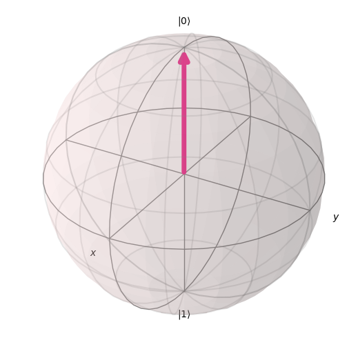
The state of a single qubit can be represented as a point on the surface of the Bloch sphere. The poles correspond to the |0> and |1> states. All other points represent superpositions of |0> and |1> defined by two angles - $\theta$ and $\phi$ in spherical coordinate $[r, \theta, \phi]$
Visualize the |0> state
import numpy as np
from qiskit.visualization import plot_bloch_vector

# You can use spherical coordinates instead of cartesian.

plot_bloch_vector([1, 0, 0], coord_type='spherical')
Visualize the |1> state
plot_bloch_vector([1, np.pi, 0], coord_type='spherical')

Pauli X (NOT) gate
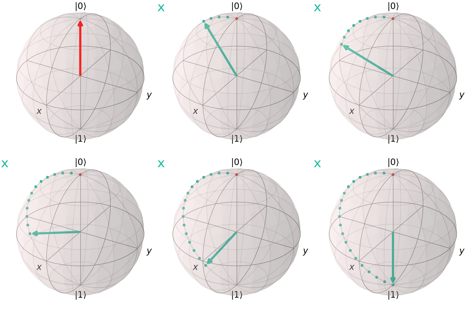
The Pauli X gate, also known as the NOT gate, performs a bit flip, transforming $|0>$ to $|1>$ and vice versa. On the Bloch sphere, it corresponds to a 180° rotation about the x-axis.
from qiskit import QuantumCircuit
qc = QuantumCircuit(1)
qc.x(0)
qc.draw('mpl')

from qiskit.visualization import visualize_transition
visualize_transition(qc, trace = True,saveas = "x_gate.gif", fpg = 20, spg = 2)
Pauli Y Gate
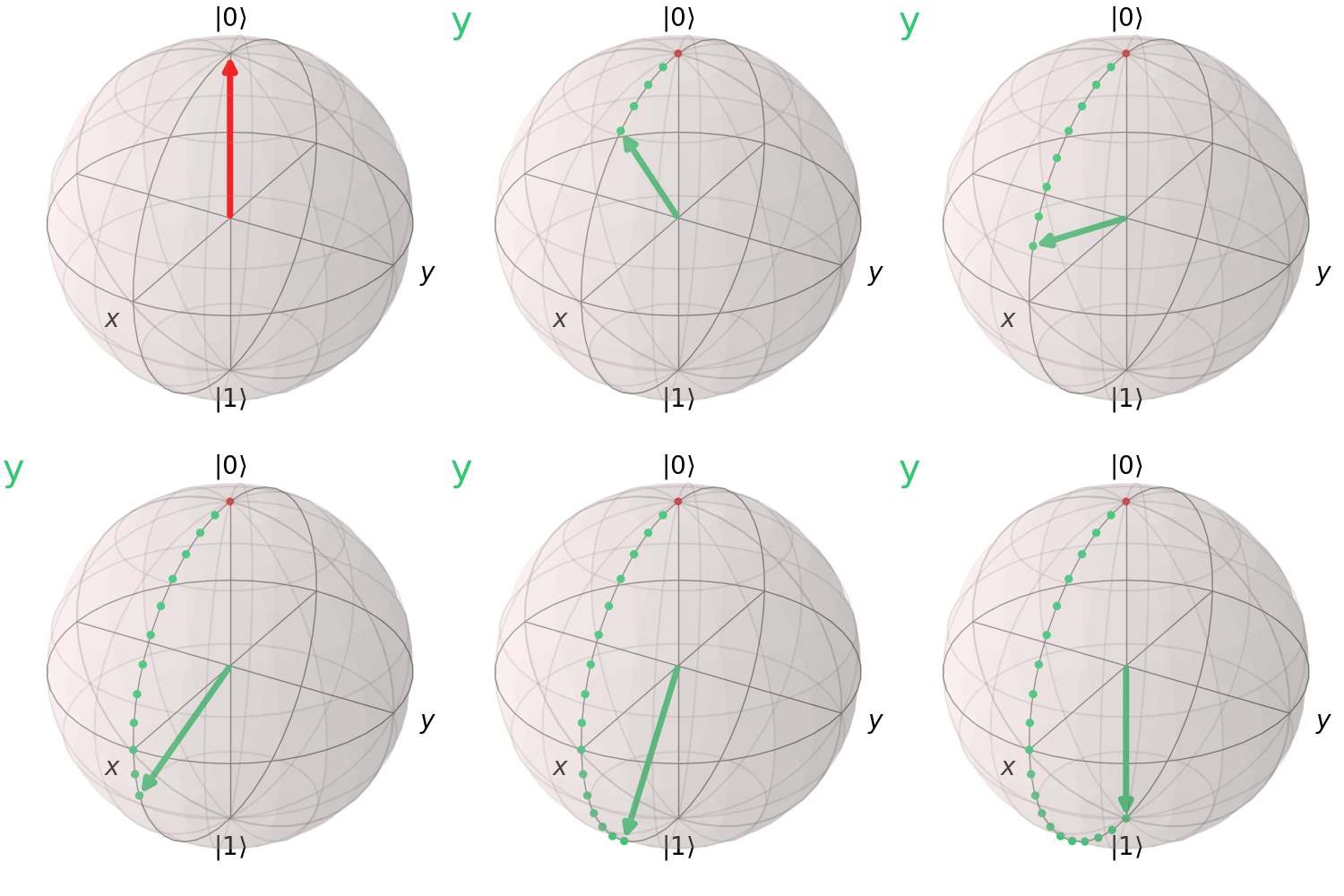
The Pauli Y gate performs a bit and phase flip. It rotates the qubit state by 180° about the y-axis.
qc = QuantumCircuit(1)
qc.y(0)
qc.draw('mpl')

visualize_transition(qc, trace = True,saveas = "y_gate.gif", fpg = 20, spg = 2)
Pauli Z Gate
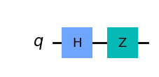
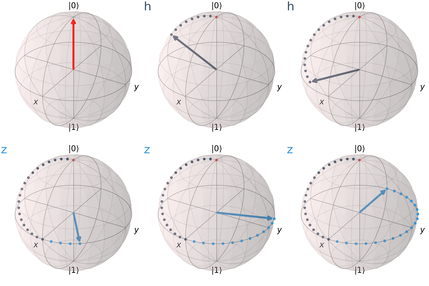
The Pauli Z corresponds to a 180° rotation about the z-axis.
qc = QuantumCircuit(1)
qc.h(0)
qc.z(0)
qc.draw('mpl')
visualize_transition(qc, trace = True,saveas = "z_gate.gif", fpg = 20, spg = 2)
Hadamard Gate
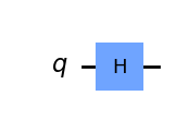
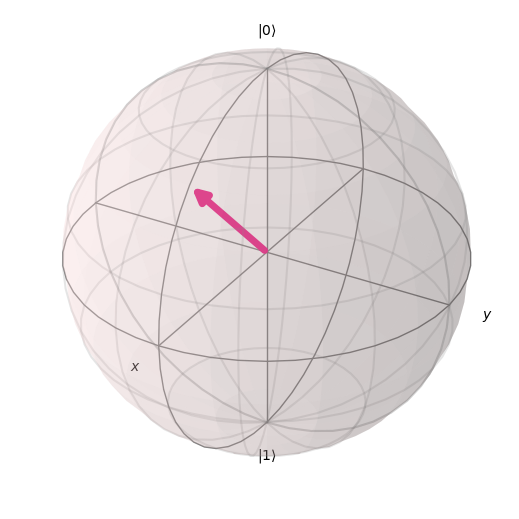
The Hadamard Gate is a fundamental element in quantum computing that applies a uniform superposition of states to a qubit. Unlike the Pauli gates, which rotate around one of the major axes, x, y, and z, the Hadamard gate rotates our quantum state by pi radians or 180 degrees around the Bloch sphere vector [1 0 1] which is the vector pointing halfway between the x-axis and the z-axis
qc = QuantumCircuit(1)
qc.h(0)
qc.draw('mpl')
Visualize the axis of H rotation
plot_bloch_vector([1, np.pi/4, 0], coord_type='spherical')
visualize_transition(qc, trace = True,saveas = "h_gate.gif", fpg = 20, spg = 3)

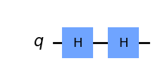
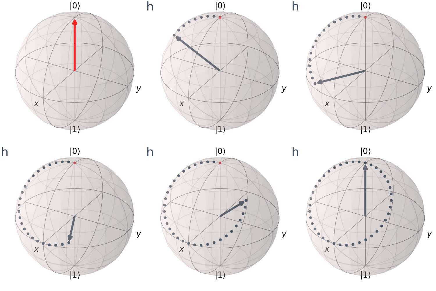
Hence, applying two consecutive H operations, we go back to the original position
qc = QuantumCircuit(1)
qc.h(0)
qc.h(0)
qc.draw('mpl')
visualize_transition(qc, trace = True,saveas = "2h_gate.gif", fpg = 20, spg = 3)
RX, RY, RZ gates
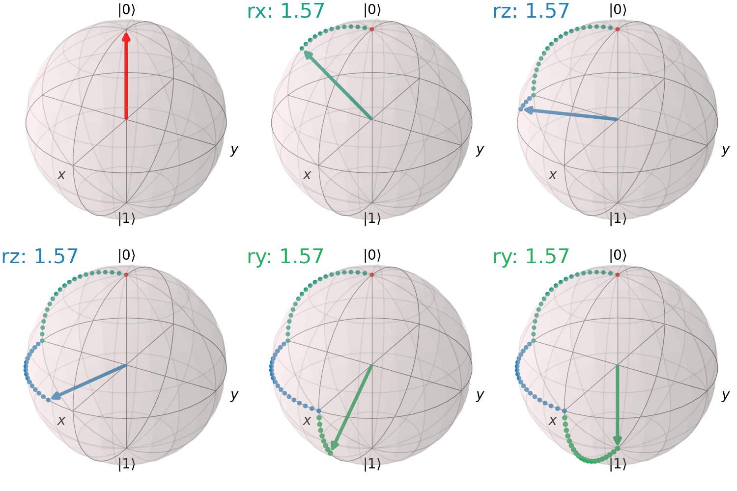
These perform arbitrary single-qubit rotations about the X, Y and Z axes. The rotation angle is specified as a parameter.
Single RX gate
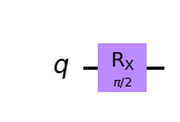
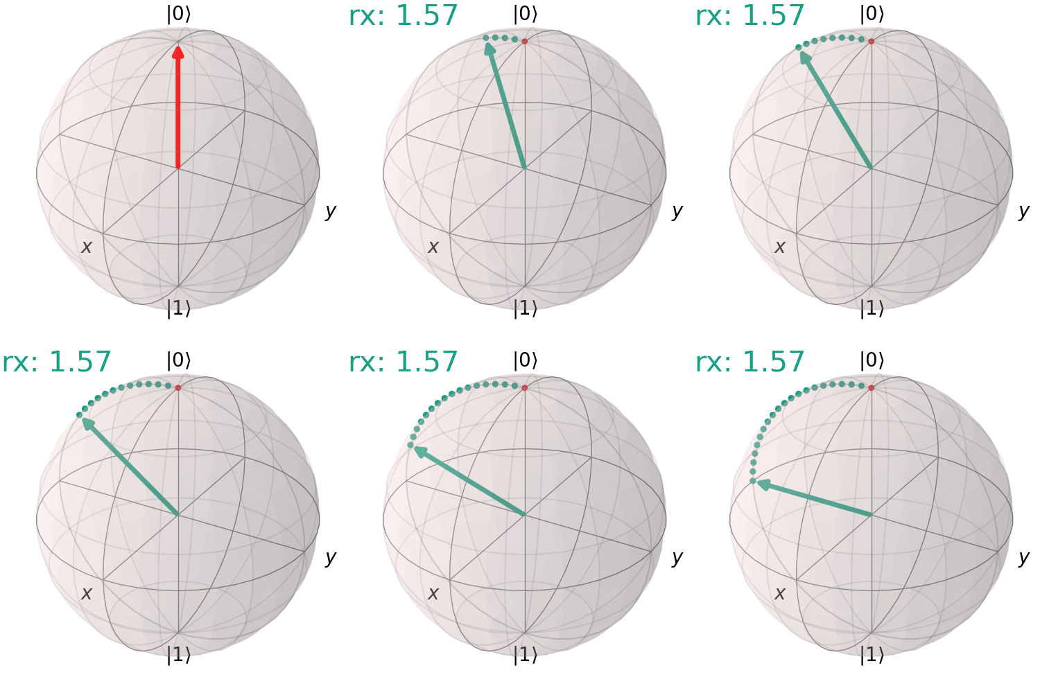
Here is an example of 90° rotation about X axis.
qc = QuantumCircuit(1)
qc.rx(np.pi/2,0)
qc.draw('mpl')
visualize_transition(qc, trace = True,saveas = "rx_gate.gif", fpg = 20, spg = 3)
Sequence of RX, RY, RZ gates
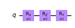
Here is an example of 90° rotation about X axis, then 90° rotation about Z axis, then 90° rotation about Y axis
qc = QuantumCircuit(1)
qc.rx(np.pi/2,0)
qc.rz(np.pi/2,0)
qc.ry(np.pi/2,0)
qc.draw('mpl')
visualize_transition(qc, trace = True,saveas = "3r_gates.gif", fpg = 20, spg = 3)
Enjoy Reading This Article?
Here are some more articles you might like to read next: